
Remote control of the High Voltage Capacitor also required some effort.
The overall reduction between the motor and the Capacitor is 1:10000. A Butterfly Capacitor only needs 90 degree rotation to go from minimum to maximum Capacity and for this loop from 3.5 to 7.2 MHz. Together with the High Q of the loop circuit it was clear a control circuit with fine tuning was needed.
 I first tried a miniature motor controller from Conrad, partnr. 245232 - 89. The kit is based on a Mitsubishi M51660L chip.
It requires an extra 556 producing a pulse with an adjustable pulse width between 1 and 2 ms.
I never figured out if I blew the chip or what but the control of the motor speed was lousy and I never could get a smooth speed control from full speed CW via no motion to full speed CCW. And yes I checked that the 1-2 ms pulses were stable and changed smoothly. Current consumption when the motor was turning very slowly or changing direction was enormous, 1-2 A! I did not even try it with RF present.
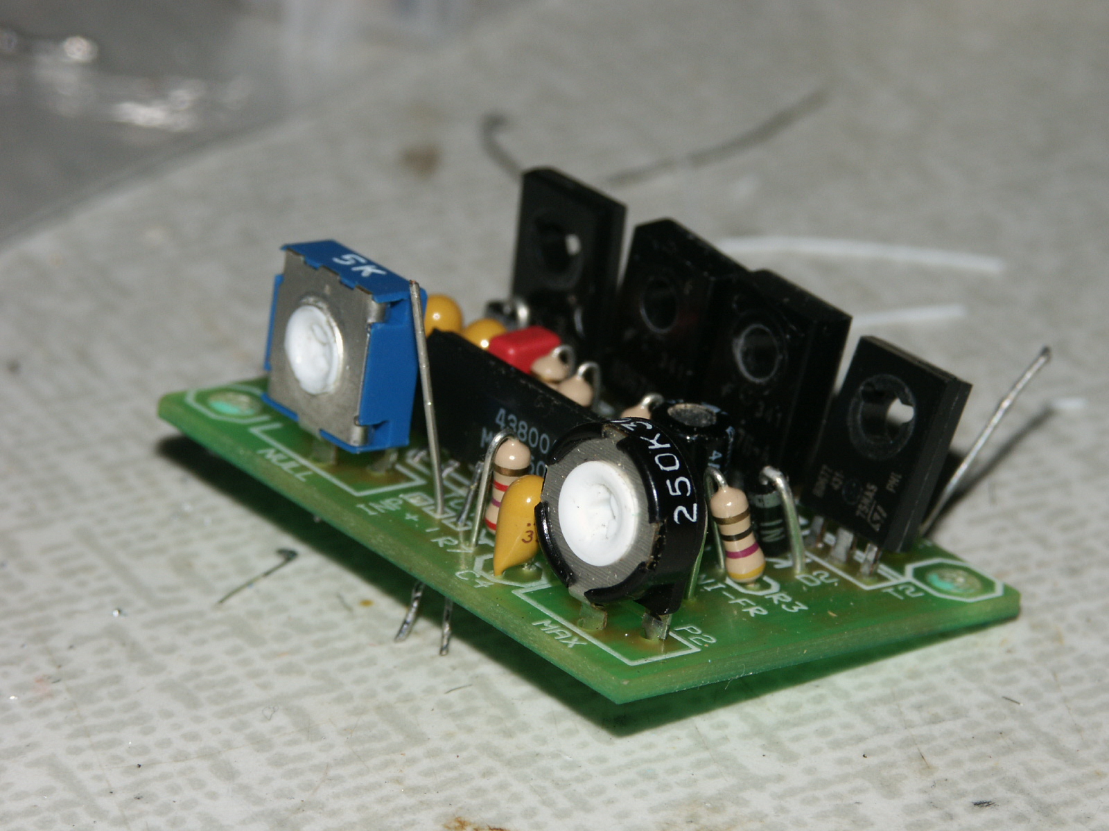
 Next try was a bi-directional motor speed control found on the internet. It's a kit sold by Kits are us model K166. I wire wrapped it together mainly from the junk box and replaced the IRF4906 by IRF9540's.
Now this circuit had a nice and smooth control of the motor speed but also two disadvantages:
- It's not natural, at least not for me, to turn the potmeter knob to the middle position when the motor must stop. Remember, you keep one eye on the VSWR indicator, the other on the Anode Current meter of the set. One hand is adjusting the rig and the other controls the antenna tuning. Maybe a joystick would have done the trick. However I felt that that was a bit overdone and I did not have one in the junk box.
- As expected the circuit was sensitive to RF. When transmitting the motor would start to turn. The potmeter needed to be adjusted again to let it stop. A few ferrite beads and decoupling caps did not solve the problem. In the end I just put a switch in series with the motor but now I had to operate a potmeter and a switch with one hand!
So I came to my senses, looked in the junk box, and built something virtually bullet proof.
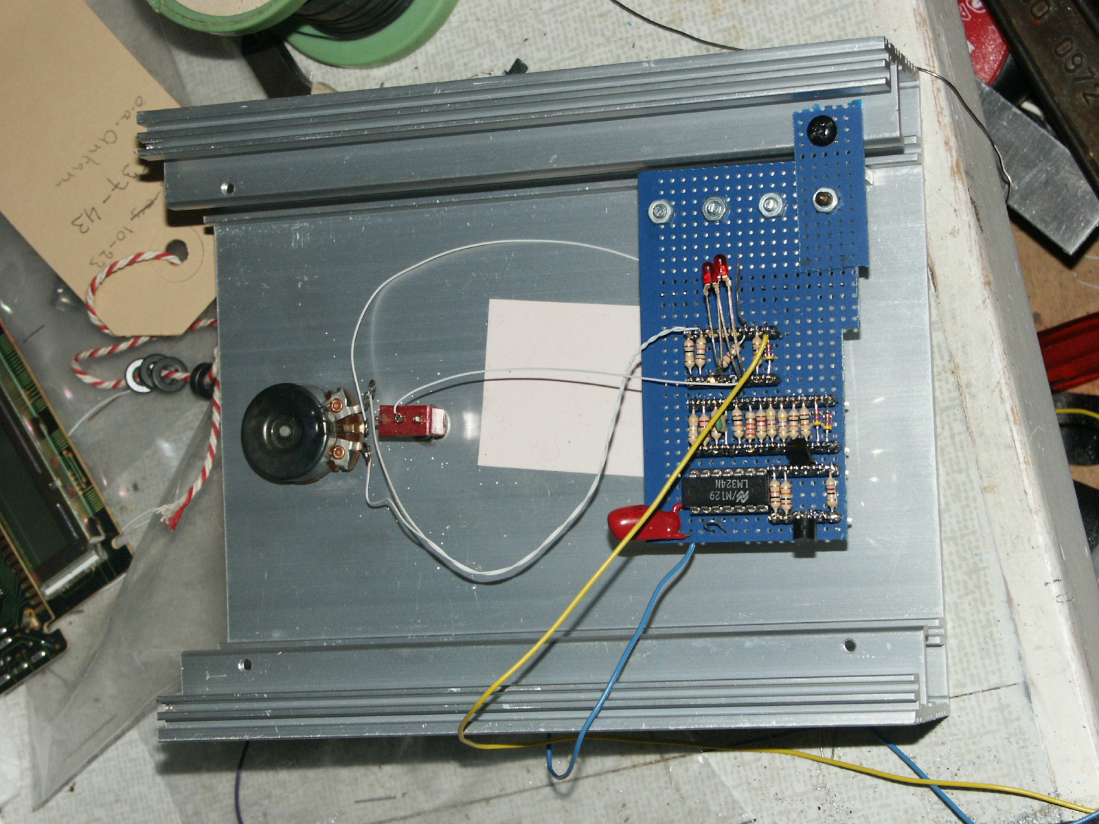
 Four relays and some diodes, controlled by 4 pushbutton switches, marked << < > >>
- A high wattage 350 ohm variable resistor (Rheostat) to control the low speed of the motor when the < or > pushbuttons are pressed.
- A Wheatstone bridge to read out the position of the Capacitor. One leg is formed by a 2.5k potmeter which can turn 360 degrees. Using a flexible coupling it is connected to the capacitor shaft. The other leg is formed by a ten turn potmeter. Bridge unbalance is measured by a 1 mA meter with a potmeter in series. Calibrate the bridge by tuning the antenna to 3.5 MHz and set the 10 turn pot. Next tune the antenna to 3.8 MHz and adjust the series resistor for the meter.
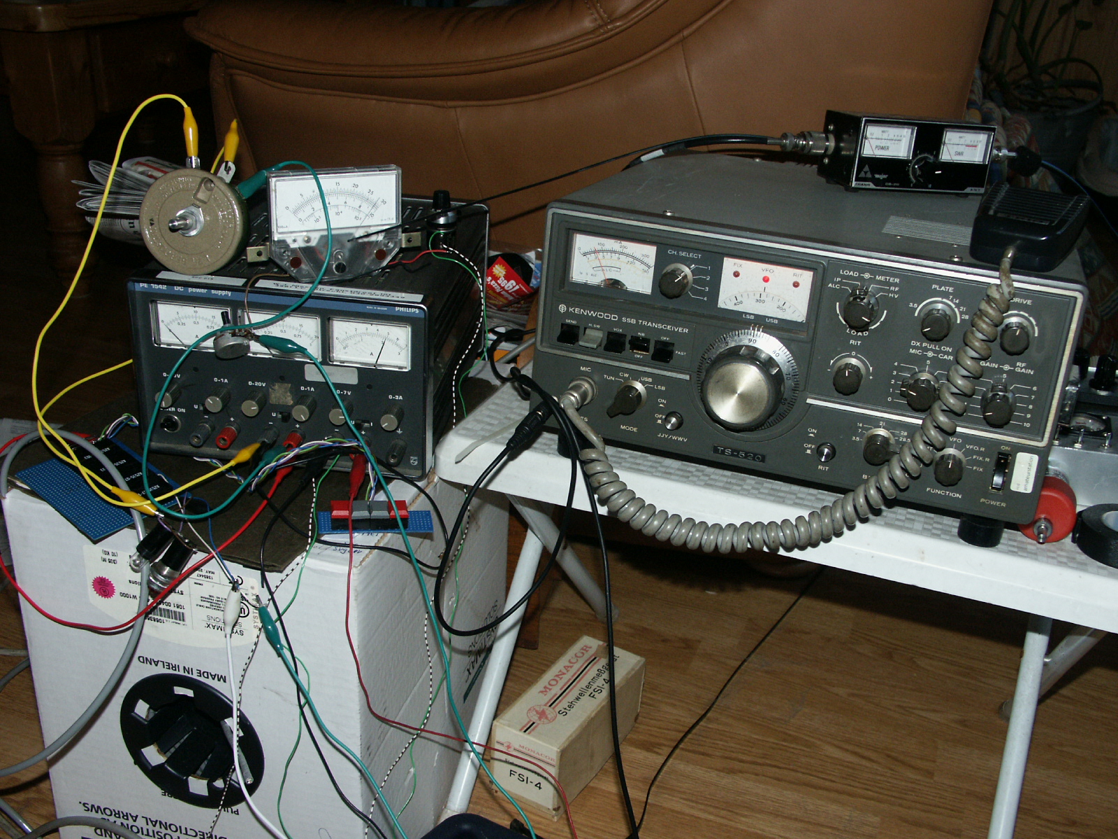
Although a straight forward circuit some extra thought went into it. If you reach the minimum VSWR you will let go of the push button. Then the motor gets shorted instead of only removing the power to it. This ensures the motor will stop as soon as possible. And that helps in not overshooting the optimum setting! The picture shows it all in a very experimental state. The meter is on top of the triple output power supply next to the Rheostat. The four red and gray pushbuttons are in front of the power supply. I'm afraid a decent housing is still some months away.
The schematics of the remote control circuit is here
The circuit works fine but like every other mag loop it requires tuning when changing frequency. Having obtained a Yaesu FT1000MP with a CAT interface the next project is an automatic Mag loop controller